
Radiographic Testing (RT)
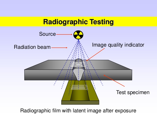
Radiography Testing the test-part is placed between the radiation source and film (or detector). The material density and thickness differences of the test-part will attenuate (i.e. reduce) the penetrating radiation through interaction processes involving scattering and/or absorption. The differences in absorption are then recorded on film(s) or through an electronic means. In industrial radiography there are several imaging methods available, techniques to display the final image, i.e. Film Radiography, Real Time Radiography (RTR), Computed Tomography (CT), Digital Radiography (DR), and Computed Radiography (CR).
Two different radioactive sources are available for industrial use: X-ray and Gamma-ray. These radiation sources use higher energy levels, i.e., shorter wavelength versions of the electromagnetic waves. Because of the radioactivity involved in radiography testing, ensuring that the Local Rules is strictly adhered to during operation is paramount.
Ultrasonic Testing (UT)
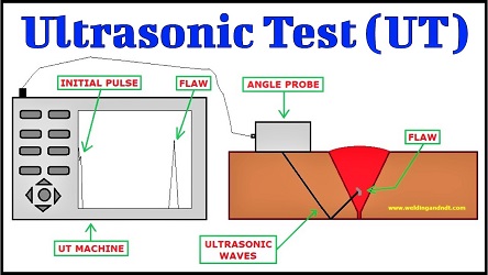
UT inspection system consists of an ultrasonic transducer, pulser/receiver, and display unit. A pulser/receiver is an electronic device that can produce high voltage electrical pulses to the transducer. When driven by the pulser, the transducer generates high frequency ultrasonic sound energy into the material in the form of sound waves.
When there are discontinuities such as inclusions, porosity, cracks, etc. in the sound path, part of the mechanical energy will be reflected from the discontinuities' (reflectors') surface.
The reflected sound waves signal received by the transducer is then transformed back into an electrical signal and its intensity is shown on the display unit.
The sound waves travel time can be directly related to the distance that the signal has travelled. From the signal, information about reflector location, size, orientation and other features can be determined.
Liquid Penetrant Testing (PT)

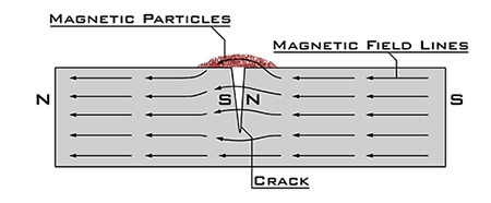
Magnetic fields to find discontinuities at or near the surface of ferromagnetic materials. The magnetic field can be created with a permanent magnet or an electromagnet, which requires a current to be applied.
The magnetic field will highlight any discontinuities as the magnetic flux lines produce leakage, which can be seen by using magnetic particles that are drawn into the discontinuity.